Physics Essay 2.7 updated Fall, 2011
Wave Harmonics
What kind of wave patterns can wave
interference lead to?
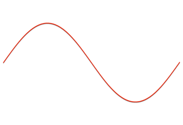
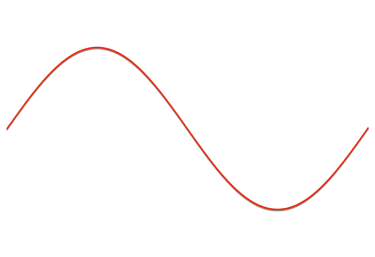
As a wave pulse travels down a slinky, it can reflect at the far end of the slinky and travel back toward the source. Figures 1 to 7 show the source wave (one wave pulse down the slinky), its reflection, and a second source wave (another wave pulse sent down the slinky) as they move, through time, along the slinky.


source wave
reflected wave
Figure 1 (Above), As a wave originates on the left, it travels down the slinky toward the right. At the right end, the wave reflects and begins to travel back towards the left.




2nd source wave
reflected wave

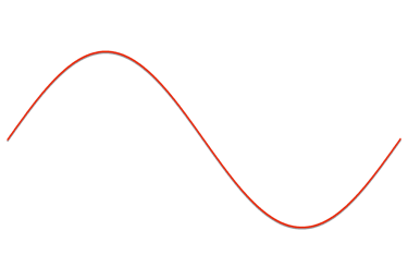
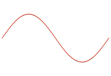

Figure 2 (Above), A second source wave pulse is initiated and now the reflected wave is traveling toward the second source wave.


2nd source wave
point where leading edge of reflected wave is meeting the leading edge of the 2nd source wave

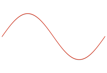
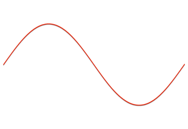

Figure 3 (Above), A short time after Figure 2, the leading edge of the second source wave pulse is just contacting the leading edge of the reflected wave. There is no interference yet.


2nd source wave


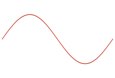

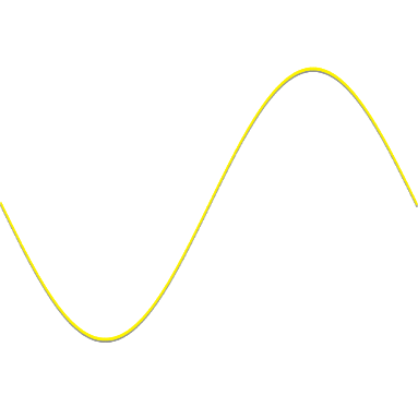
Figure 4 (Above), A short time after Figure 3, the waves are now partially overlapping and interfering. The yellow line shows the resulting position of the slinky, because of the interference between the reflected wave and second source wave.


reflected wave


Part of the second source wave interferes or combines with the reflected wave, thus the actual slinky takes the yellow position.
Part of the reflected wave interferes or combines with the source wave, thus the actual slinky takes the yellow position.


2nd source wave

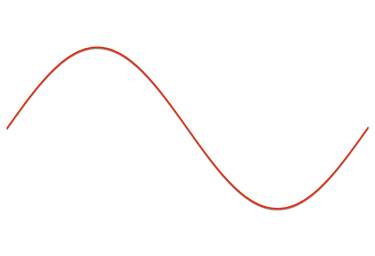
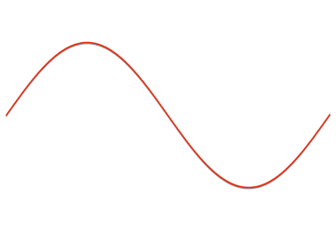

Figure 5 (Above), A short time after Figure 4, the waves are now overlapping to a greater extent and a larger portion of each wave interferes with the other. The yellow line shows the resulting position of the slinky because of the interference between the reflected wave and second source wave.


reflected wave


Part of the reflected wave interferes or combines with the second source wave, thus the actual slinky takes the yellow position.
Part of the reflected wave interferes or combines with the second source wave, thus the actual slinky takes the yellow position.



2nd source wave

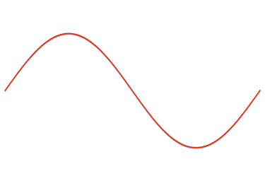

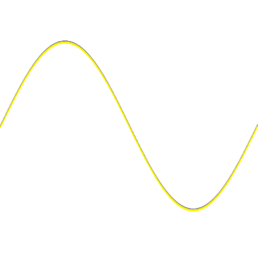
Figure 6 (Above), A short time after Figure 5, the waves are now mostly overlapping and interfering. The yellow line shows the resulting position of the slinky, because of interference.


reflected wave


Zone of no Interference
Zone of no Interference
Zone of no Interference
Zone of no Interference


Zone of no Interference
slinky position described by red line
Zone of no Interference
slinky position described by red line
Zone of Interference
Actual slinky position described by yellow line
Part of the second source wave interferes or combines with the reflected wave, thus the actual slinky takes the yellow position.
Part of the second source wave interferes or combines with the reflected wave, thus the actual slinky takes the yellow position.


Zone of Interference
Actual slinky position described by yellow line


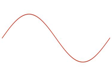
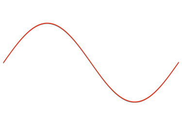
Figure 7 (Above), A short time after Figure 6, the waves are now almost entirely overlapping and interfering. The yellow line shows the resulting position of the slinky, because of interference.


Zone of no Interference
slinky position described by red line
Zone of no Interference
slinky position described by red line
Zone of Interference
slinky position described by yellow line


The series of diagrams above show the results of interference of the reflected wave and the second source wave, and how the interference pattern changes through time. For regions where there is no overlap, and so no interference, the position of the slinky is described by the red line. For regions where there is overlap, and so the waves do interfere, the position of the slinky is described by the yellow line.
Imagine a situation, similar to your harmonics experiment, where wave pules are constantly sent down the slinky and constantly reflect back. A complicated pattern of interference would arise. But, if the timing of the wave pulses is just right, a harmonic pattern can be established. This type of pattern results when certain position(s) along the slinky always experience complete destructive interference. These are positions where a reflected wave crest meets a source wave trough or a reflected wave trough always meets a source wave crest, with the destructive interference always producing ZERO amplitude in these positions. At other points along the harmonic pattern are position(s) where a reflected wave crest meets a source wave crest or a reflected wave trough meets a source wave trough, with this constructive interference producing large amplitude vibrations in these position(s). Look through all of the diagrams below to see this pattern develop over time.
The EIGHT diagrams below show a slinky’s position over time as waves move through the slinky and interfere.

Figure 8 (Above), A series of source wave pulses, moving right, meet a series of reflected waves, moving left. The YELLOW line represents the position of the slinky.

RED source wave moving right
BLUE reflected wave moving left

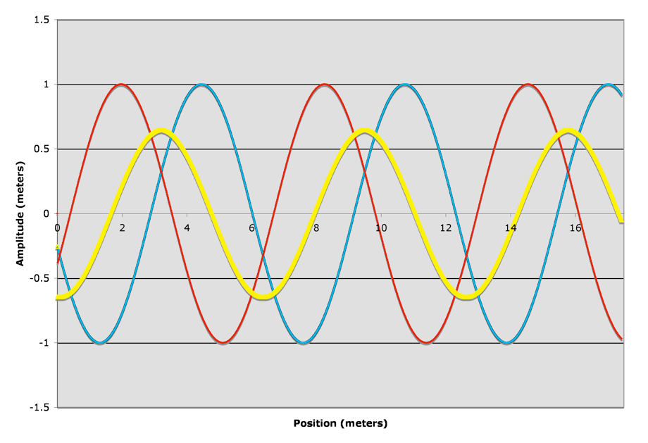
Yellow line is
the result of
interference and, therefore, actual position of slinky.
Figure 9 (Above), At a slightly later time than Figure 8, a series of source wave pulses, moving right, meet a series of reflected waves, moving left. The YELLOW line represents the position of the slinky.

RED source wave moving right
BLUE reflected wave moving left

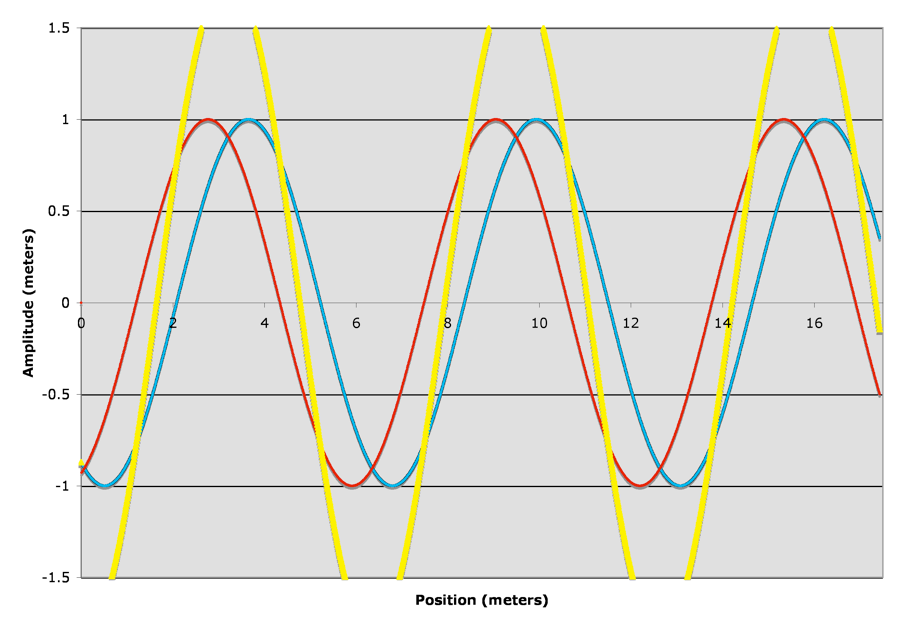
Figure 10 (Above), At a slightly later time than Figure 9, a series of source wave pulses, moving right, meet a series of reflected waves, moving left. The YELLOW line represents the position of the slinky.

RED source wave moving right
BLUE reflected wave moving left

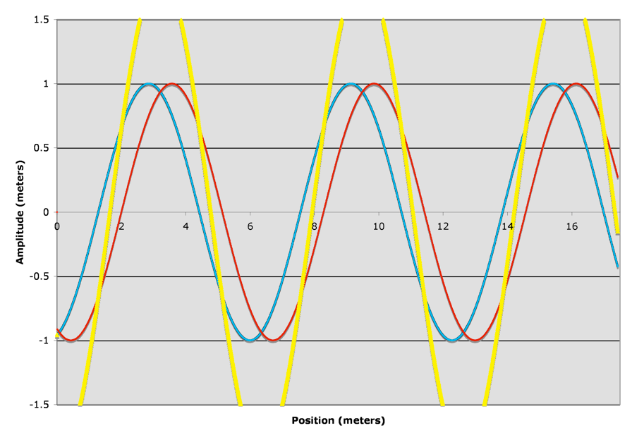
Figure 11 (Above), At a slightly later time than Figure 10, a series of source wave pulses, moving right, meet a series of reflected waves, moving left. The YELLOW line represents the position of the slinky.

RED source wave moving right
BLUE reflected wave moving left

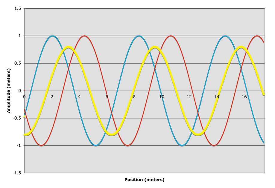
Figure 12 (Above), At a slightly later time than Figure 11, a series of source wave pulses, moving right, meet a series of reflected waves, moving left. The YELLOW line represents the position of the slinky.

RED source wave moving right
BLUE reflected wave moving left

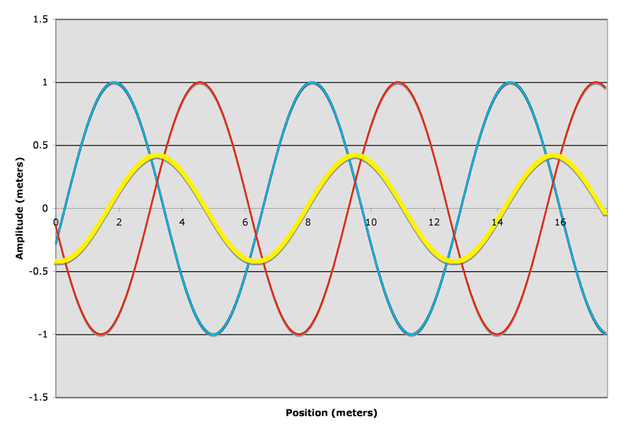
Figure 13 (Above), At a slightly later time than Figure 12, a series of source wave pulses, moving right, meet a series of reflected waves, moving left. The YELLOW line represents the position of the slinky.

RED source wave moving right
BLUE reflected wave moving left

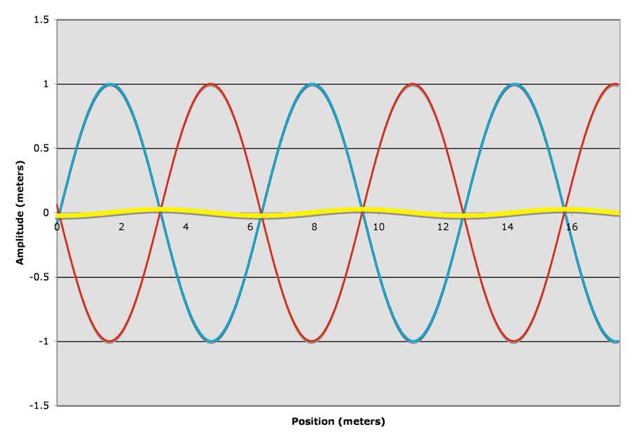
Figure 14 (Above), At a slightly later time than Figure 13, the RED source wave has moved far enough right and the BLUE reflected wave has moved far enough to the left that the pattern from Figure 8 has been reestablished. As time continues, the patterns in Figures 8 to 13 will be repeated over and over in the same sequence.

RED source wave moving right
BLUE reflected wave moving left


GREEN dots are points on slinky that have ZERO displacement.


GREEN dots are points on slinky that have ZERO displacement.


GREEN dots are points on slinky that have ZERO displacement.


GREEN dots are points on slinky that have ZERO displacement.


GREEN dots are points on slinky that have ZERO displacement.


GREEN dots are points on slinky that have ZERO displacement.

Notice as the interference pattern changes through time (from Figure 8 to Figure 13), certain points along the slinky are always at ZERO displacement. These point are shown in GREEN and are ALWAYS at the positions of 1.6m, 4.7m, 7.8m, 10.9m, 14.0m, and 17.1m. These point are referred to as nodes. The position halfway in between each pair of nodal points are where the maximum displacement occurs. These positions are referred to as antinodes.
To see this in real time with transverse waves, click here (EWS). To see a demo of this with compressional waves, click here (EWS).
To see harmonics in SOAP BUBBLES, click here (EWS). Cool!
Copyright © 2009-2012, by Marcus Milling
edited by Julia Pian
reflected wave
Yellow line is
the result of
interference and, therefore, actual position of slinky.
Yellow line is
the result of
interference and, therefore, actual position of slinky.
Yellow line is
the result of
interference and, therefore, actual position of slinky.
Yellow line is
the result of
interference and, therefore, actual position of slinky.
Yellow line is
the result of
interference and, therefore, actual position of slinky.
Yellow line is
the result of
interference and, therefore, actual position of slinky.


